

Easy Virtual Network GNS3 Lab Configuration Walkthrough
Intro to Easy Virtual Network (EVN)
When we think of virtualization we may think of vendors like VMware, Citrix, or Docker….
Cisco Easy Virtual Network? Not so much.
Until now.
Easy Virtual Network (EVN) is an end-to-end layer 3 network virtualization technology. Its primary job is to provide network path separation and isolation.
Over the years, internet service providers have kept customers traffic isolated from one another. Through different means, but if they use Cisco hardware, a cost-effective way would be via VRF/VRF-Lite.
With VRF technology Layer 3 devices maintain separate routing tables on the same device.
VRF-Lite provides the same functionality as VRF. Except, its geared more towards enterprise networks instead of service providers (i.e. MPLS).
EVN was developed from VRF-Lite. It makes improvements as it relates to path isolation and is much easier to configure overall.
In the ensuing article, we’ll walkthrough some EVN configuration.
Lab Scenario
Imagine we work for an enterprise and we want to separate network traffic. We’ve classified traffic into two categories secured and non-secured.
Traditionally, on the network, we use VLANs to categorize and separate traffic at Layer 2 creating multiple broadcast domains.
An attacker, however, can use an attack called VLAN hoping to bypass this barrier.
We decide to up the ante, by implementing Easy Virtual Network (EVN) to provide additional Layer 3 segmentation. This, in turn, creates separate routing tables for the two categories.
Tools
Here is a list of tools used to build this lab:
IPTerm – Linux based Docker container that includes various network utilities. In this lab it’s used to simulate PC clients. Its primary function will be to verify connectivity across EVNs by ping.
Cisco IOSvL2 15.2 – Image used for the two switches.
Cisco IOSv 15.6(2)T – Image used for the three routers.
GNS3 – Opensource network emulator
Topology and Base Configuration
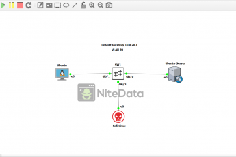
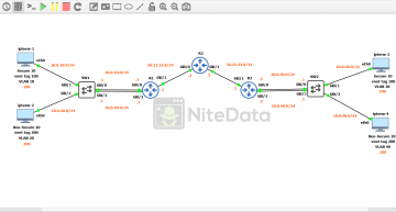
Below is how the lab topology looks like in GNS3:
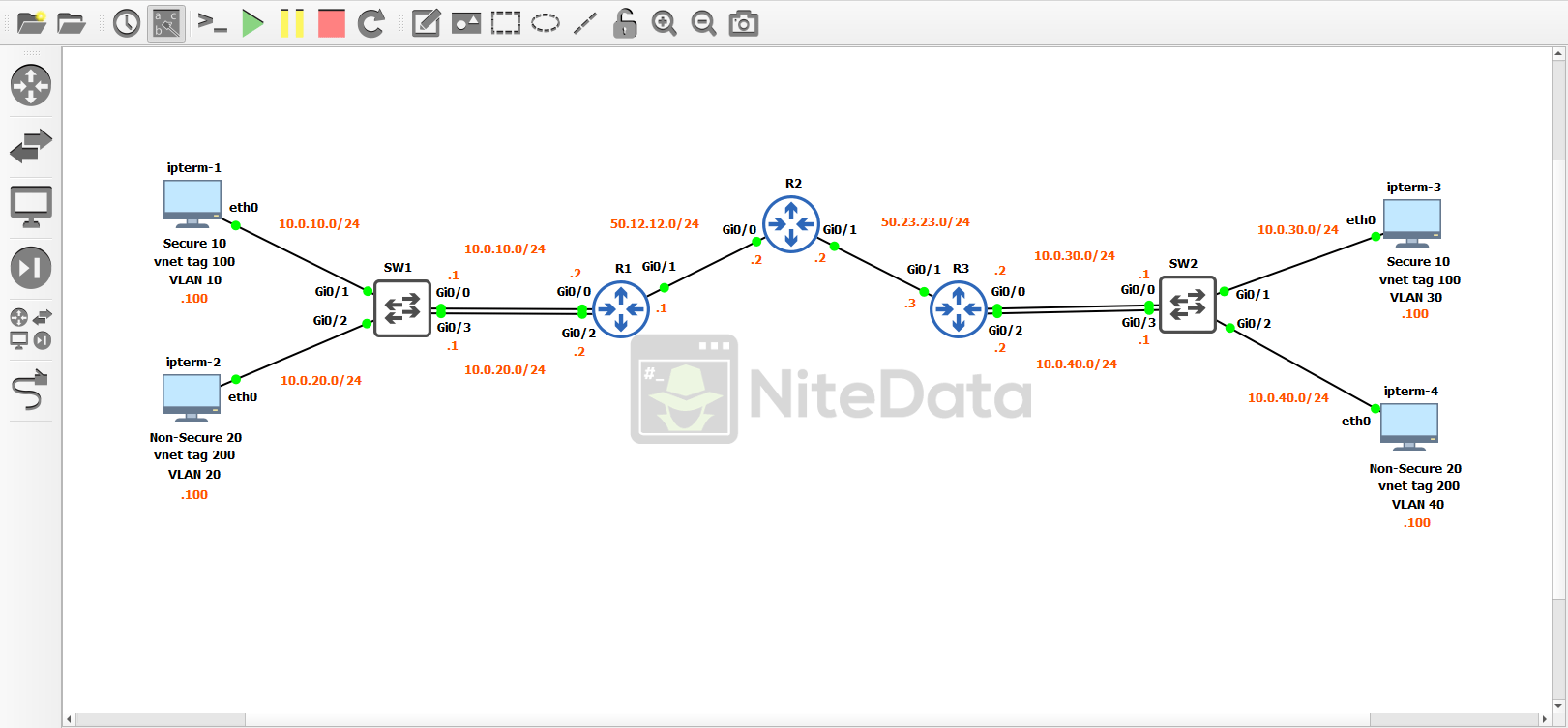
Before implementing EVN into our environment we need to go through and apply some baseline config to each device. Making sure we have basic connectivity.
IPTerm
IPTerm is a lightweight GNS3 appliance/Docker container that is comprised of Linux (Debian) based networking tools.
It’s a good way to simulate hosts on network. Providing more functionality than its GNS3 alternative VPCs and consumes less resources on our local PC than an actual VM would.
In this lab, all hosts are on different subnets with each IP address ending in .100. We need to go through and statically assign IP addresses to each of these hosts.
There are two ways to accomplish this:
- We can assign addresses through the Linux terminal.
- Edit the config file for each ipterm appliance.
In this example, I’m going to edit the config file.
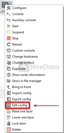
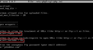
Right-click the ipterm-1 icon and select Edit Config
To statically assign addresses to the host uncomment the highlighted block:
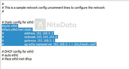
Click Save and we’re done!
We continue this process until we’ve completed all four of the ipterm clients.
After we’re done the config on each host should look like:
ipterm-1
auto eth0
iface eth0 inet static
    address 10.0.10.100
    netmask 255.255.255.0
    gateway 10.0.10.1
ipterm-2
auto eth0
iface eth0 inet static
    address 10.0.20.100
    netmask 255.255.255.0
    gateway 10.0.20.1
ipterm-3
auto eth0
iface eth0 inet static
    address 10.0.30.100
    netmask 255.255.255.0
    gateway 10.0.30.1
ipterm-4
auto eth0
iface eth0 inet static
    address 10.0.40.100
    netmask 255.255.255.0
    gateway 10.0.40.1
Cisco Switch Configuration
Now it’s time to setup the switches.
Each switch is configured with two VLANs. With each ipterm host on its own VLAN.
Let’s look at the base config on Switch 1 (SW1) and we’ll breakdown each part.
SW1
configure terminal
hostname SW1
The hostname of this switch is SW1.
vlan 10
  name SECURE
vlan 20
  name NON-SECURE
exit

int vlan 10
description SECURE
ip address 10.0.10.1 255.255.255.0
no shut

int vlan 20
description NON-SECURE
ip address 10.0.20.1 255.255.255.0
no shut
Here we create the VLANs used and the associated Switched Virtual Interfaces (SVIs). This is a Layer 3 switch, so the default gateway of each ipterm host points to the IP address of the SVI.
interface gi0/0
description SECURE UPLINK
switchport mode access
switchport access vlan 10
no shut

interface gi0/1
description SECURE
switchport mode access
switchport access vlan 10
no shut

interface gi0/2
description NON-SECURE
switchport mode access
switchport access vlan 20
no shut

interface gi0/3
description NON-SECURE UPLINK
switchport mode access
switchport access vlan 20
no shut
end
With these four interfaces, two ports represent the uplinks for the network, the other two connect directly to the clients. All ports are set to access mode and are assigned to specific VLANs.
Look closer at the diagram.
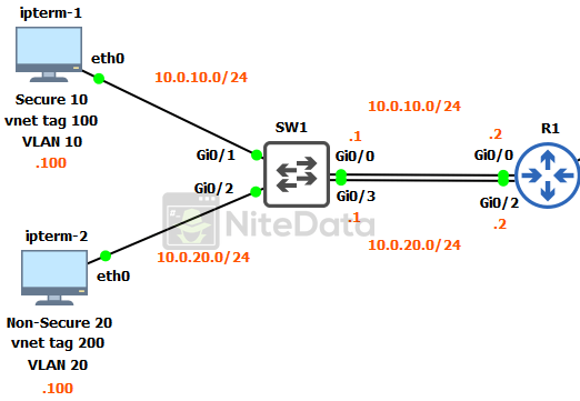
Gi0/1 and Gi0/2 directly connect to the clients. Traffic coming from the ipterm-1 client is classified as secure and is in VLAN 10, inside of the subnet 10.0.10.0/24. The vnet tag is set to 100.
The vnet tag concept is similar to the VLAN process at Layer 2. EVN tags VPN packets (at layer 3) this plays a big part in the identification of traffic throughout the network. (We will get into the configuration of vnet tags later in the Easy Virtual Network implementation section).
IPterm-2 is classified as non-secure and is in VLAN 20, inside of the subnet 10.0.20.0/24. The vnet tag is set to 200.
Gi0/0 and Gi0/3 are acting as uplinks to the router. Even though they too are access ports. The IP addresses assigned to the SVIs a little bit ago, provides the routing connectivity between SW1 and R1.
For each EVN we create, we need a separate link connection, in this case we have two. So, to reiterate:
Gi0/0 is the EVN uplink for the VLAN 10 / vnet tag 100 networks.
Gi0/3 is the EVN uplink for the VLAN 20 / vnet tag 200 networks.
SW2
Moving on to Switch 2 (SW2) we have much of the same config.
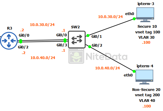
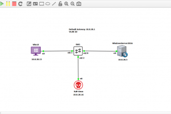
The only major differences are ipterm-3 and 4 are in different VLANs and subnets than on SW1.
Notice the vnet tags (100 and 200) are the same as they are over on SW1’s LAN.
Once Easy Virtual Network (EVN) setup is done. The hosts with the same vnet tag (ipterm-1 and ipterm-3) should be able to ping each other. But unable to communicate with the other hosts (ipterm-3 and ipterm-4) that are using vnet tag 200.
This is how SW2 is setup.
SW2
configure terminal
hostname SW2

vlan 30
  name SECURE
vlan 40
  name NON-SECURE
exit

int vlan 30
description SECURE
ip address 10.0.30.1 255.255.255.0
no shut

int vlan 40
description NON-SECURE
ip address 10.0.40.1 255.255.255.0
no shut

interface gi0/0
description SECURE UPLINK
switchport mode access
switchport access vlan 30
no shut

interface gi0/1
description SECURE
switchport mode access
switchport access vlan 30
no shut

interface gi0/2
description NON-SECURE
switchport mode access
switchport access vlan 40
no shut

interface gi0/3
description NON-SECURE UPLINK
switchport mode access
switchport access vlan 40
no shut
end
Routers Configuration
The LAN is ready to go. Time to get the routers up.
# Disclaimer – The subnet mask of /24 for the WAN interfaces uses too many IP addresses. In a production environment we would use a /30. I chose /24 for simplicity sake.
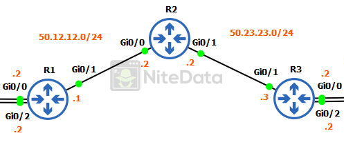
R1 and R3 are the edge routers for our two distinct LANs.
R1
We’ll go through the config of each router starting with R1.
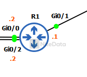
configure terminal
hostname R1

interface Gi0/0
description SECURE
ip address 10.0.10.2 255.255.255.0
no shut

interface Gi0/1
ip address 50.12.12.1 255.255.255.0
no shut
Gi0/0 is a dedicated link for secure traffic on our network. Notice the IP is 10.0.10.2 this is a point-to-point link with SW1’s VLAN 10 SVI 10.0.10.1.
Gi0/1 is the WAN interface and connects to R2. It’s using the 50.12.12.0/24 subnet range.
interface Gi0/2
description NON-SECURE
ip address 10.0.20.2 255.255.255.0
no shut

router ospf 1
network 50.12.12.0 0.0.0.255 area 0
end
Gi0/2 is a dedicated link for traffic classified as non-secure. It connects to SW1’s VLAN 20 SVI 10.0.20.1.
In the picture of our three routers, we should have noticed that the subnet between R1-R2 (50.12.12.0/24) is different than the subnet between R2-R3 (50.23.23.0/24).
To ensure we have routing between these subnets we need to turn on a dynamic routing protocol. In this lab, we are using OSPF.
On the router OSPF 1 line, we define the network we want the router to advertise. In this case, it’s 50.12.12.0/24.
R2
Next, we move on to R2.
configure terminal
hostname R2

interface Gi0/0
ip address 50.12.12.2 255.255.255.0
no shut

interface Gi0/1
ip address 50.23.23.2 255.255.255.0
no shut
Both Gi0/0 and Gi0/1 we assign IP addresses onto the local interfaces in their respective subnets.
router ospf 1
network 50.12.12.0 0.0.0.255 area 0
network 50.23.23.0 0.0.0.255 area 0
end
Then enable OSPF on the interfaces.
R3
Finally, we configure R3 to complete our base configuration.
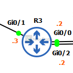
configure terminal
hostname R3

interface Gi0/0
description SECURE
ip address 10.0.30.2 255.255.255.0
no shut

interface Gi0/1
ip address 50.23.23.3 255.255.255.0
no shut
Gi0/0 is a dedicated link for secure traffic. Its local interface IP 10.0.30.2 connects to SW2’s VLAN 30 SVI 10.0.30.1.
Gi0/1 is the WAN interface connected to R2. Its subnet range is 50.23.23.0/24.
interface Gi0/2
description NON-SECURE
ip address 10.0.40.2 255.255.255.0
no shut

router ospf 1
network 50.23.23.0 0.0.0.255 area 0
end
Gi0/2 is a dedicated link for traffic classified as non-secure on our LAN going to SW2. Connects to VLAN 40 SVI 10.0.40.1 on SW2.
To round it off, we enable OSPF on the WAN interface (network 50.23.23.0).
If we can ping across from R1 to R3.
We can then begin configuring EVN.
Easy Virtual Network Implementation
Now that we have our base configuration in place. We’re ready to create some path isolation for network traffic specified as either secure or non-secure.
Switch Configuration
We start off configuring the switches before moving to the routers.
SW1
configure terminal

vrf definition SECURE
 vnet tag 100
 address-family ipv4
  exit-address-family
  exit

vrf definition NON-SECURE
 vnet tag 200
 address-family ipv4
  exit-address-family
  exit
First, we define our VRFs and associate it with a specific vnet tag value.
int vlan 10
vrf forwarding SECURE
ip address 10.0.10.1 255.255.255.0
no shut

int vlan 20
vrf forwarding NON-SECURE
ip address 10.0.20.1 255.255.255.0
no shut
Next, we go onto the SVIs and assign the VRF definitions to the interfaces.
#Note entering the command vrf forwarding will reset IP address configuration on the interface. The IP address will need to be assigned again.
Because EVN/VRF paths have their own routing tables separate from the OSPF global configuration we setup earlier. We need to configure a routing protocol specifically for the VRF instances.
In this lab, I’m going to use EIGRP.
router eigrp SECURE
First, we create a named EIGRP instance. The name can be anything. In this example, it’s named SECURE.
address-family ipv4 vrf SECURE autonomous-system 1
Here we identify the IP version, then the specific VRF definition and apply it to the anonymous-system number we’re using.
network 0.0.0.0
It’s now time to classify the networks we want to advertise in this VRF instance. Because this is a lab, I’m using 0.0.0.0 to advertise all available networks found. In production, we would want to define the networks specifically.
We follow the same EIGRP process for the NON-SECURE VRF definition.
router eigrp NON-SECURE
address-family ipv4 vrf NON-SECURE autonomous-system 1
network 0.0.0.0
end
SW2 is the same configuration as SW1. Here is how the config should look.
SW2
configure terminal

vrf definition SECURE
 vnet tag 100
 address-family ipv4
  exit-address-family
  exit

vrf definition NON-SECURE
 vnet tag 200
 address-family ipv4
  exit-address-family
  exit

int vlan 30
vrf forwarding SECURE
ip address 10.0.30.1 255.255.255.0
no shut

int vlan 40
vrf forwarding NON-SECURE
ip address 10.0.40.1 255.255.255.0
no shut

router eigrp SECURE
address-family ipv4 vrf SECURE autonomous-system 1
network 0.0.0.0

router eigrp NON-SECURE
address-family ipv4 vrf NON-SECURE autonomous-system 1
network 0.0.0.0
end
Routers Configuration
We have EVN setup on the switches. Now we move to the routers to bring it on home.
R1
configure terminal

vrf definition SECURE
 vnet tag 100
 address-family ipv4
  exit-address-family
  exit

vrf definition NON-SECURE
 vnet tag 200
 address-family ipv4
  exit-address-family
  exit
Here we define our VRFs and associate it to a specific vnet tag value. Just like we did on the switches.
interface Gi0/0
vrf forwarding SECURE
ip address 10.0.10.2 255.255.255.0
no shut

interface Gi0/1
vnet trunk

interface Gi0/2
vrf forwarding NON-SECURE
ip address 10.0.20.2 255.255.255.0
no shut
On Gi0/0 and Gi0/2 we associated the VRF definitions to the interfaces connecting back to the switch. Then we reassign IP addresses to the interfaces.
Gi0/1 is handled differently its configured as a vnet trunk. It connects to R2.
VNET trunks are similar in concept to your prototypical layer 2 trunks. They allow for multiple vnet tagged packets to traverse across a single link. If we didn’t use a vnet trunk, we would have to create an additional physical link per EVN between each network device.
router eigrp SECURE
address-family ipv4 vrf SECURE autonomous-system 1
network 0.0.0.0

router eigrp NON-SECURE
address-family ipv4 vrf NON-SECURE autonomous-system 1
network 0.0.0.0
end
EIGRP configuration is the same as it was on the switches.
The configurations on R2 and R3 are similar to R1’s.
R2
Here is the output from both R2:
configure terminal

vrf definition SECURE
 vnet tag 100
 address-family ipv4
  exit-address-family
  exit

vrf definition NON-SECURE
 vnet tag 200
 address-family ipv4
  exit-address-family
  exit

interface Gi0/0
vnet trunk

interface Gi0/1
vnet trunk

router eigrp SECURE
address-family ipv4 vrf SECURE autonomous-system 1
network 0.0.0.0

router eigrp NON-SECURE
address-family ipv4 vrf NON-SECURE autonomous-system 1
network 0.0.0.0
end
R3
EVN setup is the same on R3.
configure terminal

vrf definition SECURE
 vnet tag 100
 address-family ipv4
  exit-address-family
  exit

vrf definition NON-SECURE
 vnet tag 200
 address-family ipv4
  exit-address-family
  exit

interface Gi0/0
vrf forwarding SECURE
ip address 10.0.30.2 255.255.255.0
no shut

interface Gi0/1
vnet trunk

interface Gi0/2
vrf forwarding NON-SECURE
ip address 10.0.40.2 255.255.255.0
no shut

router eigrp SECURE
address-family ipv4 vrf SECURE autonomous-system 1
network 0.0.0.0

router eigrp NON-SECURE
address-family ipv4 vrf NON-SECURE autonomous-system 1
network 0.0.0.0
end
Verification
At this point, we are finished!
Time to verify our configuration is working properly.
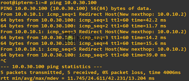
From ipterm-1 we should be able to ping ipterm-3 successfully. Because they both been assigned to the same VRF / VNET tag 100.
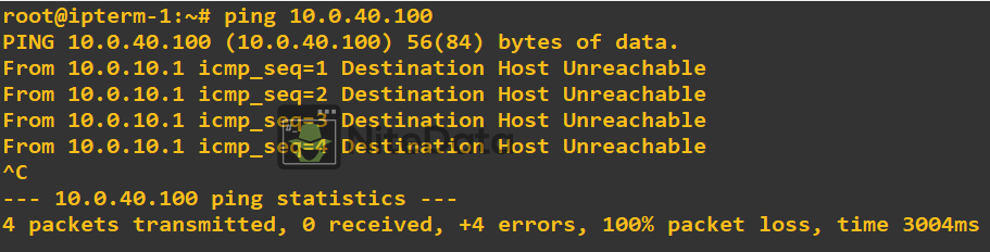
However, we should be unsuccessful when we ping from ipterm-1 to ipterm-4. Because their paths have been isolated due to EVN. Remember, VNET tag 200 is associated with both ipterm-3 and ipterm-4.
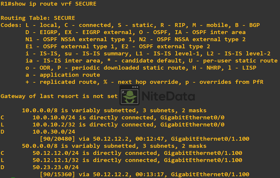
We also have the ability to use show commands on our cisco devices to verify connectivity and/or configuration.
Examples:
show ip route vrf SECURE
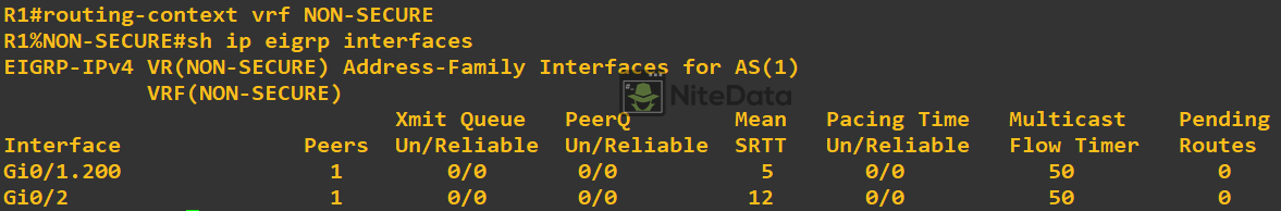
show ip eigrp vrf NON-SECURE interfaces
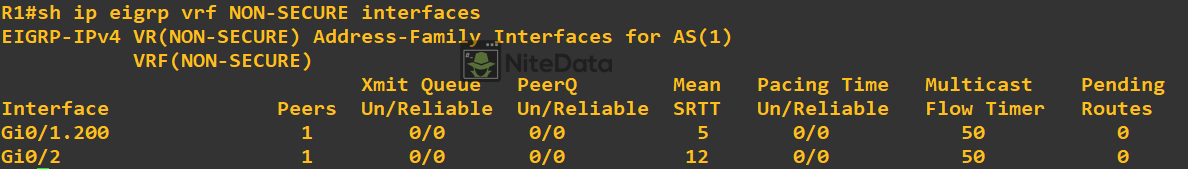
Notice for the previous show commands, we had to specify the VRF we wanted to see output for.
Routing-context command allows us to drop into a VRF virtual instance. All commands that run inside this instance are specific to the VRF. Allowing us to omit the VRF keyword at the end of each command.
routing-context vrf NON-SECURE
In this lab, we have gone through the configuration of EVN and seen how it can be applied in a production environment.
Leave a Comment